Hello,
I’ve made an ATtiny84 with RFM95w module and BME280 environment sensor. Total code size: 7212 bytes, data: 139 bytes.
Maybe you can use this as starting point for your ATmega168.
Hello,
I’ve made an ATtiny84 with RFM95w module and BME280 environment sensor. Total code size: 7212 bytes, data: 139 bytes.
Maybe you can use this as starting point for your ATmega168.
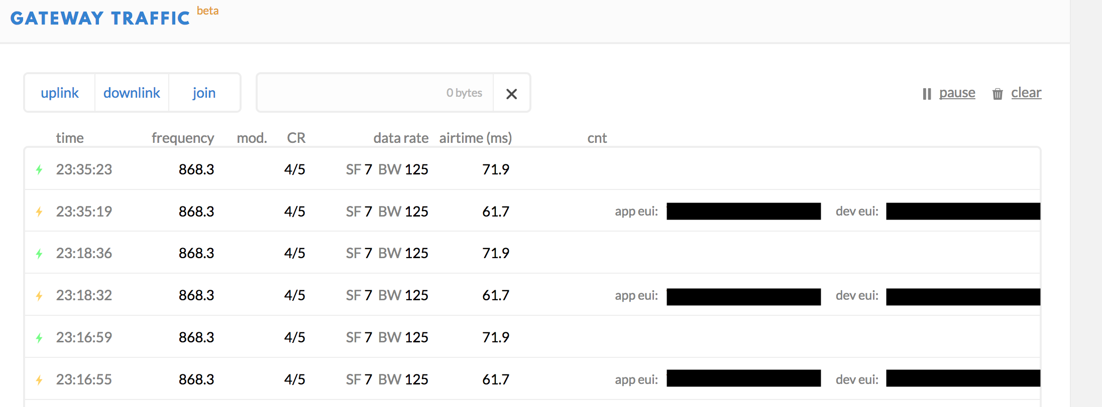
@mvdswaluw: The same near Eindhoven:

Time is in UTC, first column SNR, second RSSI.
Thanks! I’ll give it a try tonight and see if I can get the program to work.
I did try that already without any luck…
I also tried to write other types of modes to it, but it does always stay in sleep mode (0x00). So something happens when I write RH_RF95_LONG_RANGE_MODE(0x80) as it then goes to RH_RF95_ACCESS_SHARED_REG(0x40) for some reason?
Note: When the device starts the register reads 0x40 (RH_RF95_ACCESS_SHARED_REG).
Is it working or not ? On your previous post you said you only get gateway’s coordinates. So yes, I do not get it 
If so what does mean "I did the HTTP integration to my test server and on that server i get payload data with latitude and longitude. " ?
No, the flag set internally by the LoRa device, when the device decides it is ready.
I wrote some thing a little bit confused xD Yes it is working OK. In my console i see the location of my device.
So there is see coordinates of my device shown be side the map. So my main question is how to store or parse or something like that coordinates which are shown be side the map?
I think I should not even mention the HTTP integration because there is no connection here. Let’s just leave that behind.
I really hope that you understand me now?
Great !
Unfortunately we will not be present but we are happy to see the community growing and soon become an official TTN community.
We will soon visit our colleagues from Montpellier who told us they are beginning three tests for their experiments in wheat fields, grapevines and trees !
Have a nice meetup !
I scoured the forums trying to find more information regarding the Dragino GPS + Lora Shield, but I was not able to find too much stuff that I can work with directly. I did try to implement the verification of sending the data via the simulated downlink on the TTN console itself, but I cannot get the Raspberry Pi Gateway to acknowledge the transmission of data (via downlink):
preparing a downlink package

downlink package scheduled, but does not want to transmit. I notice that after a while it disappears from the data list despite it not being sent / received on the Rpi.

no downlink package received in the raspberry pi itself; it does update periodically, which is nice

//////////////////////////////////////////////////////////////////////////
Alternatively, I tried to implement the LMIC method as described on the Dragino wiki, but this also does not bear fruit. Although I can install and alter the necessary files (specifically, alter the Device Address/ Network Key and App Key according to the key(s) from TTN Console) I cannot get the LMIC to succesfully transmit:


Although it claims that pin 4 cannot be found, this is not referenced in the pin mapping below as I have changed the pin mapping to what is recommended on the Dragino wiki.


DIO1+DIO2 of HPD13A LoRa Chip are now wired on the pcb to GPIOs of the ESP32, so no more external wiring is required for LMiC operation.
Besides that they changed the battery charging circuit. Now an IP5306 chip holds the charging logic, unfortunately still without digital connection to CPU for battery probing.
I already added a suitable hal-file to my paxcounter software, but couldn’t test it yet.
Hi,
Seems that some confusion abounds…
What I understand is that
I am not sure if you can/how to do that. But will look into it.
The Collos integration can forward said coordinates formatted as a GPS device to any Cayenne integration that you have though.
Hi @Nanne118
for downstream message , did you follow my instructions ?
Hi @Batigolle
After the installation of the gateway software (sudo make install of dual_chan_pkt_fwd) I have ensured that the global_conf.json file has the correct parameters:

I am not using an arduino setup to transmit the sensor values (as I will instead be using an identical raspberry pi with lora hat as a client or node to sent data from to my gateway), so I should be able to downlink data to the gateway directly, correct?
What determines the possibility of downstream, is the gateway software, as a sensor you can have the type you want
@Batigolle
So it actually has to have a sensor sending data towards the gateway for the downlink to function? How does it then know to send this data via the node? Is there any way to verify that the gateway is working from the console?
From what I understood the downlink functions to send data from the TNN ‘‘down’’ to the gateway, as opposed to the uplink of data normally (eg from a sensor connected to a lora node). Would that be correct?
yes
From what I understood and that I verified with the tests, the sequence is …
Start transmission …
… End of Transmission
maybe, someone more experienced, can correct my statements if they contain errors
Hi,
I am running a Raspberry Pi with IMST iC880A gateway with the poly_pkt_fwd package forwarder running. I try to get OTAA working but struggle with the join_accept messages. I can see that TTN is sending join_accept messages and some matching messages in the package forwarded (where I am not 100% sure if they belong to the join_accept, but it´s really likely) but the node does not seem to get it:
+RESET: OK
+ID: DevAddr, 00:0E:34:03
+ID: DevEui, 00:D8:C0:83:E7:A0:3F:70
+ID: AppEui, 70:B3:D5:7E:D0:00:ED:A2
+ID: DevEui, 00:D8:C0:83:E7:A0:3F:70
+ID: AppEui, 70:B3:D5:7E:+KEY: APPKEY 6A1CF732D2AE94C759F1B9F77530E861
+MODE: LWOTAA
+DR: EU868
+DR: DR0
+DR: EU868 DR0  SF12 BW125K
+CH: 0,868100000,DR0:DR5
+CH: 1,868300000,DR0:DR5
+CH: 2,868500000,DR0:DR5
+CH: 3,867100000,DR0:DR5
+CH: 4,867300000,DR0:DR5
+CH: 5,867500000,DR0:DR5
+CH: 6,867700000,DR0:DR5
+CH: 7,867900000,DR0:DR5
+RXWIN1: ERROR(-1)
+RXWIN2: 868300000,DR3
+ADR: OFF
+LW: DC, OFF, 0
+LW: JDC, OFF
+POWER: 2
+JOIN: Start
+JOIN: NORMAL
+JOIN: LoRaWAN modem is busy
+JOIN: Join failed
+JOIN: Done
Logs from the gateway:
##### 2018-05-15 21:36:50 GMT #####
### [UPSTREAM] ###
# RF packets received by concentrator: 0
# CRC_OK: 0.00%, CRC_FAIL: 0.00%, NO_CRC: 0.00%
# RF packets forwarded: 0 (0 bytes)
# PUSH_DATA datagrams sent: 1 (215 bytes)
# PUSH_DATA acknowledged: 0.00%
### [DOWNSTREAM] ###
# PULL_DATA sent: 3 (100.00% acknowledged)
# PULL_RESP(onse) datagrams received: 0 (0 bytes)
# RF packets sent to concentrator: 0 (0 bytes)
# TX errors: 0
### [GPS] ###
# Invalid gps time reference (age: 1526420210 sec)
# Manual GPS coordinates: latitude 53.85579, longitude 10.73494, altitude 0 m
##### END #####
INFO: [down] for server router.eu.thethings.network PULL_ACK received in 62 ms
The code I use on the node:
//#include "LoRaWan.h"
#include<LoRaWan.h>
#include "keys.h"

//#define FREQ_RX_WNDW_SCND_US  923.3
#define FREQ_RX_WNDW_SCND_EU  869.525
/*#define FREQ_RX_WNDW_SCND_AU  923.3
#define FREQ_RX_WNDW_SCND_CN  505.3
#define FREQ_RX_WNDW_SCND_KR  923.3
#define FREQ_RX_WNDW_SCND_IN  866.55
#define FREQ_RX_WNDW_SCND_AS1 923.3
#define FREQ_RX_WNDW_SCND_AS2 923.3*/

//const float US_hybrid_channels[8] = {903.9, 904.1, 904.3, 904.5, 904.7, 904.9, 905.1, 905.3}; //rx 923.3
const float EU_hybrid_channels[8] = {868.1, 868.3, 868.5, 867.1, 867.3, 867.5, 867.7, 867.9}; //rx 869.525
/*const float AU_hybrid_channels[8] = {916.8, 917.0, 917.2, 917.4, 917.6, 917.8, 918.0, 918.2}; //rx 923.3
const float CN_hybrid_channels[8] = {487.1, 487.3, 487.5, 487.7, 486.3, 486.5, 486.7, 486.9}; //rx 505.3
const float KR_hybrid_channels[8] = {922.1, 922.3, 922.5, 922.7, 922.9, 923.1, 923.3, 0};     //rx 921.9
const float IN_hybrid_channels[8] = {865.0625, 865.4025, 865.9850, 0, 0, 0, 0, 0};            //rx 866.55
const float AS1_hybrid_channels[8] = {923.2, 923.4, 922.2, 922.4, 922.6, 922.8, 923.0, 922.1}; //rx 923.2
const float AS2_hybrid_channels[8] = {923.2, 923.4, 923.6, 923.8, 924.0, 924.2, 924.4, 924.6}; //rx 923.2*/

//United States Receive Window Data Rate = DR8
//#define DOWNLINK_DATA_RATE_US DR8
#define DOWNLINK_DATA_RATE_EU DR8
/*#define DOWNLINK_DATA_RATE_AU DR8
#define DOWNLINK_DATA_RATE_CN DR0
#define DOWNLINK_DATA_RATE_KR DR0
#define DOWNLINK_DATA_RATE_IN DR2
#define DOWNLINK_DATA_RATE_AS1 DR2
#define DOWNLINK_DATA_RATE_AS2 DR2*/

//#define US_RX_DR DR8
#define EU_RX_DR DR8
/*#define AU_RX_DR DR8
#define CN_RX_DR DR0
#define KR_RX_DR DR0
#define IN_RX_DR DR2
#define AS1_RX_DR DR2
#define AS2_RX_DR DR2*/

//United States max data rate for uplink channels = DR3
//#define UPLINK_DATA_RATE_MAX_US  DR3
#define UPLINK_DATA_RATE_MAX_EU  DR5
/*#define UPLINK_DATA_RATE_MAX_AU  DR3
#define UPLINK_DATA_RATE_MAX_CN  DR5
#define UPLINK_DATA_RATE_MAX_KR  DR5
#define UPLINK_DATA_RATE_MAX_IN  DR5
#define UPLINK_DATA_RATE_MAX_AS1 DR5
#define UPLINK_DATA_RATE_MAX_AS2 DR5*/

//#define MAX_EIRP_NDX_US 13
#define MAX_EIRP_NDX_EU  2
/*#define MAX_EIRP_NDX_AU 13
#define MAX_EIRP_NDX_CN  7
#define MAX_EIRP_NDX_KR  4
#define MAX_EIRP_NDX_IN 13
#define MAX_EIRP_NDX AS1 5
#define MAX_EIRP_NDX_AS2 5*/

//The min uplink data rate for all countries / plans is DR0
#define UPLINK_DATA_RATE_MIN DR0

#define DEFAULT_RESPONSE_TIMEOUT 5
unsigned char frame_counter = 1;
int loopcount = 0;

char buffer[256];


void setup(void)
{
    SerialUSB.begin(115200);
    while(!SerialUSB);

    lora.init();
    lora.setDeviceReset();

    memset(buffer, 0, 256);
    lora.getVersion(buffer, 256, 1);
    SerialUSB.print(buffer);

    memset(buffer, 0, 256);
    lora.getId(buffer, 256, 1);
    SerialUSB.print(buffer);

    lora.setId(NULL, DEV_EUI, APP_EUI);
    lora.setKey(NULL, NULL, APP_KEY);

    lora.setDeciveMode(LWOTAA);
    lora.setDataRate(DR0, EU868);
    setHybridForTTN(EU_hybrid_channels);

    lora.setReceiceWindowFirst(868.3,  EU_hybrid_channels[0]);
    lora.setReceiceWindowSecond(FREQ_RX_WNDW_SCND_EU, DOWNLINK_DATA_RATE_EU);

    lora.setAdaptiveDataRate(false);

    lora.setDutyCycle(false);
    lora.setJoinDutyCycle(false);
    lora.setPower(MAX_EIRP_NDX_EU);

//        SerialUSB.print("Starting OTTA Join.\n");
//    loopcount = 0;
//    while(true) {
//        loopcount++;
//        if (lora.setOTAAJoin(JOIN))
//            break;
//    }
//    SerialUSB.print("Took ");
//    SerialUSB.print(loopcount);
//    SerialUSB.println(" tries to join.");
    while(!lora.setOTAAJoin(JOIN));
    //lora.loraDebug();
}

void setHybridForTTN(const float* channels){
    for(int i = 0; i < 8; i++){
        if(channels[i] != 0){
            lora.setChannel(i, channels[i], UPLINK_DATA_RATE_MIN, UPLINK_DATA_RATE_MAX_EU);

        }
    }
}

void loop(void)
{
    while(!lora.setOTAAJoin(JOIN));
    bool result = lora.transferPacket(&frame_counter, 1, DEFAULT_RESPONSE_TIMEOUT);

    if(result)
    {
        delay(50);
        frame_counter++;
        short length;
        short rssi;

        memset(buffer, 0, 256);
        length = lora.receivePacket(buffer, 256, &rssi);

        if(length)
        {
            SerialUSB.print("Length is: ");
            SerialUSB.println(length);
            SerialUSB.print("RSSI is: ");
            SerialUSB.println(rssi);
            SerialUSB.print("Data is: ");
            for(unsigned char i = 0; i < length; i ++)
            {
                SerialUSB.print("0x");
                SerialUSB.print(buffer[i], HEX);
                SerialUSB.print(" ");
            }
            SerialUSB.println();
        }
    }

    lora.loraDebug();
    delay(1000);
}
I am running out of ideas, I think the problem is not on ttn side since there I can see the join accept messages:
Do you have any ideas?
@Batigolle
Thank you, your help is appreciated massively! 
I have been doing some more testing (mostly trial and error) and I believe that I now sort of understand (with your explanation) how it should work.
I am trying to get the sensor node working now, but as shown in the image, I am hitting a snag due to the incorrect labelling of the pins themselves.
Do you also posses the Dragino GPS/Lora HAT and could you tell me your version / pinout? I have the HAT v1.4
Respect !!!
Wich techno, Mesh BT? Definitively not LoRa compliance 


